Special Notice for European Union (EU) viewers. Due to the GDPR, you are NOT AUTHORIZED to access this website for any purpose whatsoever. Continued use is a violation of US LAW.
See the disclaimer for more information.
|

This should actually be a feature that is installed on every RV - a water alarm system. In this project, you can build a multi-channel water alarm for your RV. So why is this alarm system so unique?
The system consists of a monitor located in the central control panel (or anywhere else you desire) and sensor modules located in the various areas of the RV that might be prone to a wet condition. Multiple sensors are connected to the montior; as few as one, or as many as 9 (or even more). The monitor has 3 Channels or Zones (if you are familiar with the alarm industry), and the sensors are attached to one of the zones. Of course, if you have more sensors than zones, and multiple sensors can be attached to each zone. There are no restrictions as to which sensor goes to which zone, other than a system limit based on the 750mA power limit of the monitor and worst-case power consumption requirement for alarming sensors. A zone is a logical grouping of multiple sensors. For example, in the wet bay of your RV, you may have the water pump, water heater, and plumbing fixtures. One or multiple sensors could be attached to one Zone that monitors the Wet Bay. Another zone could have one-or-more sensors in the Kitchen, and the third Zone for the bathroom, and so on. The zones should be physical areas in the RV, and with each sensor monitoring that area attached to that zone. That way, if a sensor alarms, you only have to look in the area covered by that zone rather than inspecting the entire RV.
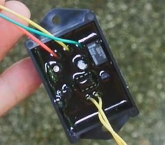
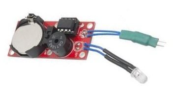
A typical sensor (shown on the right) is built on a circuit board, then encapsulated in an electronic "potting compount" which waterproofs it. The sensors are inspired by Nathan Seidle's "H2OHNO!" water-alarm project. However, it is highly modified. Still Nathan's work made designing the sensor for the Water-Alarm quick and easy. The H2OHNO! design is in the public domain (as well as the RV-Project design), so there are no rights issues. In fact, if you only require a single monitor, you can build a H2OHNO! module. While they are no longer commercially available (they used to be sold by SparkFun), you can buy a 3rd party circuit board from OSHPark, parts from various suppliers, and download the sketch from SparkFun.
So, how do the RV-Project sensor boards differ from the Sparkfun design?
In reality, the hardware design of the sensor is completely different. But some of the snippets in the sketches are similar or the same, including 3rd party sketche snippets found in the public domain.
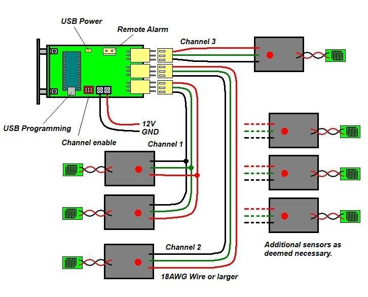
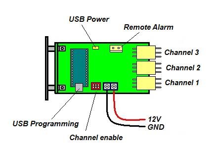
A set of "dry" relay contacts are provided for any alarm condition that may occur. Currently there is no RV-Project provided module to extend the alarms (there may be in the future). If you decide on your own device, limit the sense voltage to 12VDC@1A maximum. There are three Channels on the monitor. They are controlled by an on-board enable switch, which allows any combination of channels to be active. Channels that are turned off are simply ignored (however they are still powered by the monitor if still connected). Sensor load. The estimated sensor load in the OK or non-alarm mode is approx 1mA. This value was calculated then confirmed with an ammeter. In alarm conditions, the load is approx 20mA. If all sensors were to be in the alarm condition simultaneously, a total of 37 sensors could theoretically be supported. Self-Calibration. Since the sensors are monitor powered, there is an issue with the length of wiring between the sensors themselves and the monitor. When the monitor is first powered up (or if the reset button is pressed), the monitor will compare the output voltage to the return voltage of the sensors on each channel. It will then calculate a voltage loss and calibrate the alarm trip threshold accordingly. For this reason, the monitor should work in any RV environment (having 30ft of distance or less between the sensors and monitor), without having to re-program the sketch for the monitor.
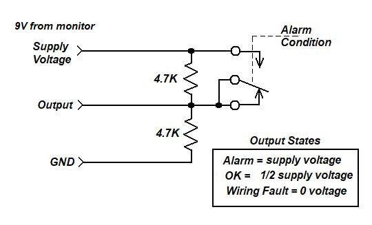
The output voltage of the Monitor is a regulated 9VDC. After cable-length loss, the voltage at the supply voltage pin of the sensor may be reduced by as much as a volt. The sensor divides this voltage by 50%, and returns the voltage to the monitor. Assuming the same 1V drop, as low as 7V=(SupplyVoltage-1v)-1v may be detected by the monitor's channel input in an alarm state, and 3V=((SupplyVoltage-1v)/2)-1v in a non-alarm state. The monitor assumes the input (3V) is 50% of the supply voltage to the sensor, so it assumes 6V will reach the input when the sensor alarms, so it calibrates the alarm threshold at 4.5V, which is a point half-way between 6V and 3V.
Even with the 1V error (expecting 6V during an alarm, but receiving 7V), the threshold of 4.5V is enough to trip the alarm and compensate for cable-length voltage loss. In a wiring fault condition, defined by an open in either supply-voltage or output of the sensor, 0V will be on the sensor input on the monitor. A second threshold setting that detects less than 1V will be tripped in the monitor and a fault-alarm condition will be assumed.
To build the project, you first need to download the documentation packet. This packet includes schematics, drawings, bill-of-materials and parts sources, as well as step-by-step instructions on building the monitor. Unfortunately, to get everything to fit into the small areas of the panel, I had to use Surface Mount Devices. These can be harder for the novice to solder, but with practice, it becomes almost easy. To help, I have used 1206 size devices, which are among the largest you can commonly obtain. You will also need a couple of circuit boards. These can be purchased from OSHPark (I have no affiliation with them). However, the minimum order is 3 boards of one kind, so you might as well make 3 sensor boards (or multiples of three).
Two different types of microcontrollers are used in this project; the venerable Atmel ATTiny85 which is used for many RV-Project.Com projects, and the introduction of a more powerful Arduino Nano microcontroller. The ATTiny85 microcontrollers are used for the sensors (each sensor has one), while the Nano is used for the monitor. Therefore when programming the microcontrollers, you will have to setup the Arduino IDE environment for an ATTiny85 for each sensor, then setup the IDE for a Nano. This is quite simple as all you have to do is to make a few changes in a menu on the Arduino IDE.
If this is your first microcontroller project, especially using the ATTiny85, you will have to setup an Arduino IDE on your Windows PC or MAC. IDE means "Integrated Development Environment"; a fancy word for an app.
The above link should sufficiently get you going with the Arduino IDE. Once you have the IDE up and running you will have to upload the sketch (firmware - or program) the Ardunio Nano, and as many Arduino ATTiny85s as sensors you are building. When uploading the sketch, be sure to burn the ATTiny85 for an 8Mhz internal clock. You don't need to do that for the Nano.
The sketches for both microcontrollers are here:
Programming the Monitor Panel. To upload sketches to the Arduino Nano, perform the following:
At this point, you can download sketches or perform any other required operations from the Arduino IDE. Reverse the steps to return the monitor to normal operation.
You will also need a front panel, ordered from Front Panel Express. A template is available from my website whereby you can order the panel. You will want panel WA-1.
Project video.
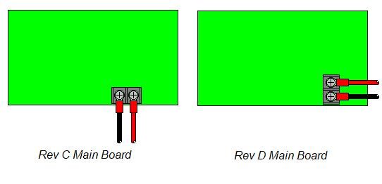
Since the original project and video, I made a revision to the main board by rotating the fuse, power connector, and D1 by 90 deg. as shown below. This allows the board to slide in and out of the mounting hole easier (Rev C often required you to remove the power connection to do so). Otherwise, the boards are identical.
 |