
Special Notice for European Union (EU) viewers. Due to the GDPR, you are NOT AUTHORIZED to access this website for any purpose whatsoever. Continued use is a violation of US LAW.
See the disclaimer for more information.
|
Time Domain Reflectometry - testing Satellite Coax Cable in a RVThe wisdom around the campfire these days it that there are a lot of bad satellite and TV coax installations being done by RV manufacturers. It's fitting I suppose as it seems to reflect the state of craftsmanship coming out of Elkhart County, Indiana these days. And my RV is no exception. So far, I have found a staple in the coax, use of too many splitters and barrel connectors, too sharp of a bend in the coax, and other issues. If I took the RV to a dealer, they would probably use a DC multi-meter and check for continuity... and seeing no shorts between the center-conductor and shield would call it good. However, an ohms check is not sufficient as I will show. Unfortunately the typical dealer (and likely the manufacturer) has neither the equipment or skills required to perform advanced analysis. This often requires a piece of electronic equipment called a TDR (Time Domain Reflectometer). A TDR is a specialized piece of electronic test equipment that is used to determine the integrity of a transmission line - including coaxial cable. They can cost several thousands of dollars, so they are not going to be part of the typical dealer's inventory. But wouldn't it at least be nice if the factory TDR tested the coax in each RV as it left the plant? Wishful thinking, I know.
Earlier in my professional career I used a Tektronix 1502 TDR. It was a nice piece of equipment, but cost several thousand dollars - back in the mid 1970s. Yea, I am dating myself, but TDRs are not something new, they have been around for at least 50 years. So how does a TDR work? In a nutshell, a TDR is kind of like radar for a cable. A pulse is transmitted down the line, and and any changes in impedance will be reflected back to the source. A display is used to show the results. A TDR typically combines an Oscilloscope, Pulse Generator, and calibration circuitry into one package. The concept is simple, but the execution of that concept can cost a lot of money.
Changes in impedance are typically associated with connectors, kinks in the wire, opens and shorts, and any anomaly that presents a mis-match of the characteristic impedance of the coax. The shape, height, and distance of the return pulse can reveal many things; the signal loss in the cable (which all cables have), length of the cable or length to the anomaly, and in some cases, the type of the anomaly. 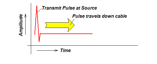 When a pulse is transmitted by the TDR, it shows up on the oscilloscope as a spike as shown above. The speed at which the pulse travels is approximately the speed-of-light divided by the cable's characteristic propigation factor. If we know the propigation factor of the cable, we can then calculate the distance from the TDR for each point along the display. For example, the popular Belden 1694 coax has a propigation factor of 80%. Thus, if we divide the speed of light by 80%, we know how far the pulse travels in a given amount of time. If we had a commercial TDR, it would be calibrated to provide that information by simply entering the propigation factor of the cable. 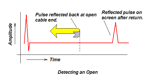 If a problem is found in the cable, energy is reflected back as shown here. The reflection will be seen by the oscilloscope at twice the time span as when it occured. This is because the reflection must travel back to the source which takes the same amount of time as the spike reaching the reflection. Again, if we had a calibrated TDR, we could measure the exact distance by diving the time from the initial spike to the reflection by 2. And if we purposely left the distant end open (i.e. not connected to anything), then 100% of the pulse should be returned. However, as shown below, we will always see less than 100% on the display. This is due to the natural attenuation of the signal presented by the cable. And since we are seeing a reflection of the pulse, it had to take a round trip (to the open and back). Therefore, the signal experienced (hopefully equal) loss on the trip out and the trip back. Therefore, simply dividing the loss by 2 should give us an accurate loss of the signal traveling down the cable. 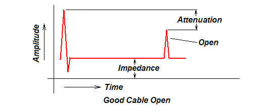 We can also change the frequency of the transmitted pulse, not only to measure the frequency respones, but to measure different lengths of cable. A higher frequency pulse will measure shorter cables, and lower frequency pulses can measure longer cables - usually up to several kilometers. 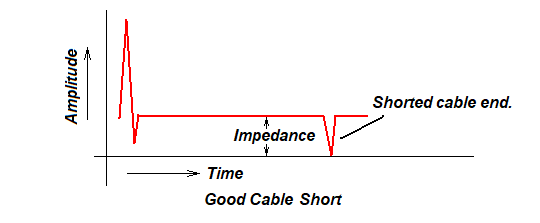 Conversely, if we short the cable, we will see a negative spike at the short. Thus, an open is a positive spike, and a short is a negative spike. Remember we are looking at a voltage that is in-sync with the cable's impedance. An open is of course infinate ohms, and a short is 0 ohms. One neat trick is if you alternately short and open the distand cable end, you can see the spike on the oscilloscope also change from positive to negative. This is useful to identify which spike is the cable end. 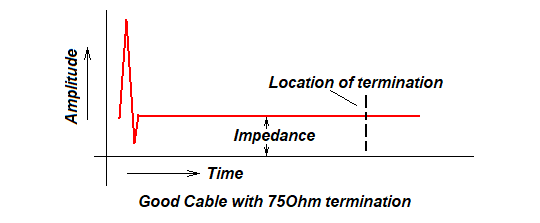 And if we properly terminate the cable at the far end with a 75ohm terminator (load), then we should not see any reflection at all. Ideally, it should be a perfectly flat line that goes on forever (or until the next generated spike). So from a TDR we can obtain the integrity of the cable, it's length, loss in amplitude along that length, and frequency response. This is a lot more comprehensive than a simple Ohmmeter. The one issue with a TDR is learning to intrepret the result. I suppose it is not unlike an electrocardiogram, where a set of trained eyes are required to provide an analysis. But with a bit of experience, it does not take long to figure a few things out.
Yes, you can build a TDR.
The parts are pretty much stock items, and with the exception of the integrated circuit, they are very easy to find. The 74AC14N cannot be substituted, but can be found at DigiKey.Com as of this writing. The Bill-of-Materials is shown below, and corresponds to the components used in the circuit board - not the schematic. While the capacitors are surface mount, they are 1206, which is fairly large, and should not present a problem for anyone with a bit of experience in soldering. Obtain the circuit board here: OSH Park
Hint. Since you have to order a minimum of 3 circuit boards from OSHPark - why not buy enough parts to make three TDRs (plus a couple of spare parts should you lose one during assembly) Note that in the future, I will (hopefully) be working with Tomi to make a nicer version of the TDR... one that fits into a nice case for ease of use. If that happens, I will post the updated circuit here. The largest expense you will have is the purchase of an Oscilloscope and 12V Power Supply. The Oscilloscope should be at least 50Mhz and have an external trigger input. This is in the realm of a hobby-grade scope, but you can still spend $200-400, so this is probably not a justifiable expense if you will only use the scope with the TDR. Don't discount the used market. eBay often has tube scopes for $100 or less, and there are websites that recondition old scopes as well. Avoid those cheap hand-held Shenzhen Marketplace scopes on Amazon and eBay that are often in kit form. They just don't have the high-frequency response required for a TDR.
What is all this talk about a Trigger? A trigger in scope terms is simply a signal that synchronizes the display so that it is stable. Without a trigger, you may not be able to view the display. If you are old enough, you might remember adjusting the "Horizontal Hold" in your parent's old TV set. A trigger is similar to that function. As you view the scope screen shots below, you will see a blue trigger input. My scope uses an input channel to trigger another channel (for example the Blue Channel 2 input can be used to trigger the Yellow Channel 1 input). For that reason, the trigger trace is shown on-screen. Other scopes however do not have a displayable trigger. Just depends on the scope.
The highest frequency for this TDR is around 50Mhz. Keep that in mind as the typical satellite down-link can be as high as 1Ghz. It would just be cost prohibitive for a hobbyist to obtain a scope that fast. Still, the losses at 1Ghz will be greater, so even at 50Mhz, we can be confident that the issues we find at 50Mhz will be multiplied at 1Ghz. 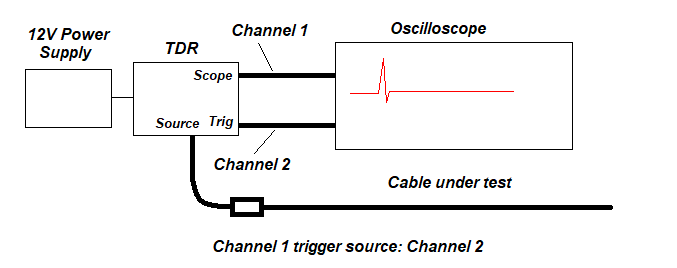 The exact connection of the TDR depends on how your scope's trigger input is configured. For my scope, any channel can be configured as a trigger for any other channel, so I setup Channel 2 to be a trigger for Channel 1. A trigger is a timing pulse that ensures a the display is synchronized to the TDR - in otherwords, to obtain a stable display. 
The test setup looks rather crude, but it does the job.
Testing the CablesThe first test was for a known good cable, 50ft long. This was done for two purposes. First it validated that the TDR is functioning properly, and I will be using this cable in every test, which not only represents the Antenna-to-RV coax, but also to minimize any blind spots.  You will see two traces here. The blue trace on top can be disregarded. It is the trigger signal. The bottom Yellow trace is the TDR trace we want to examine. There are quite a few things we can learn here. First, the signal pulse is shown with a positive and negative spike. The width of this spike will mask any problems during the pulse generation, so it is wise to always have a short "feeder" cable. Since this will end up becoming the feeder cable, we want to look at it first. The open is shown as a positive spike. The loss in amplitude looks to be around 25% of the spike. And since this is round trip, we need to divide that loss by 2 - so about 12% signal loss over 50ft. Fifty-feet of RG6 should have around 1dB or less signal loss at 50Mhz (the speed of the TDR pulse), so that looks about right. the really short line that represents the cable response shows a flat line as it should be. This is one limitation to an inexpensive TDR, it doesn't have the best resolution... however, it is accurate enough. Finally, the subsequent reflections beyond the open are harmonic ringing and can pretty much be disregarded. 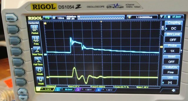 If we short out the cable at the far end, we can see a negative going spike down to 0V. This is the expected TDR behavor. Again, we can disregard any ringing after the negative spike. 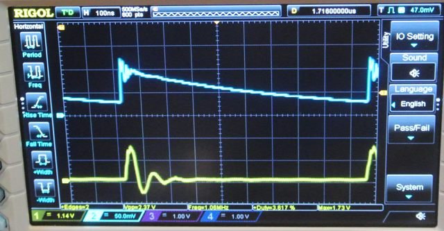 Next, we put a 75ohm terminator on the cable. It pretty much flattens out, which is what we want to see. There is a bit of a spike at the terminator location - most likely caused by the barrel connector. Overall though, the cable looks good.  Next, I connected the cable we just tested to the RV's satellite coax, so that we will now measure both cables in together. And as you can see from the result, it looks ugly. I marked the open of the cable, but were the two question marks are show two problem areas. One high impedance area and one slightly low impedance area. Something is not right here. And look how much lower the open amplitude is commpared to the spike. That has to be at least a 35% loss in signal. I ended up tearing the RV apart and replaced every barrel connector I could find with a higher quality "F-81 blue" barrel as well as tightened every connection. Here are the results: 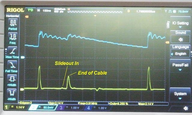 Now that is much better. There is still a small blip along the cable which I don't like, but overall much improved. And it looks like we reduced the signal loss to around 25%. 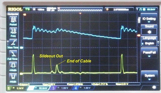 So one other thing to try. The last test was done with the slideout room in. Since the cables flex when the slideout is extended and retracted, lets extend the slideout to it's fully extended position. Uh Oh. We now see a problem. That blip is apparently the cable that extends and retracts with the slideout. And we are now back up to around 30% loss. This is marginal at best, and will only get worse over time. I am sure the cable is being continuously bent at a sharp angle. So I ended up running my own satellite cable. I cut down to 1 barrel connector - where the antenna coax connects to the RV coax. I also eliminated the barrel connector at the receiver by eliminiating the wall plate. 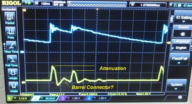 And here is the new coax installation. Still a bit of a blip in the coax, which is likely the one-and-only barrel connector. Although I did manage to put a kink in the cable during the final part of the installation - after everything was buttoned up (why does it always happen at the end of the job), so it might be that as well. So I will likely be replacing it if I still have performance issues. But that is another project. On the loss side, it looks to have a 15% loss, which is acceptable.
ConclusionReading a TDR is almost like reading an electrocardiogram I suppose, as it does take some intrepretation to look at all of the nuances. But I was able to see barrel connectors, calculate the estimated signal loss, and most incredible, a difference when the slideout flexed the cable. That was a bit surprising. So a TDR is certainly a valuable tool in the RV toolbox. It probably isn't for everybody, but if you have the wherewithall, it is worth building one.
Project video.
|
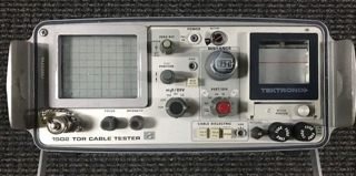
 The main difference with this TDR when compared to a commercial version is it does not have the range or resolution in the display, and it is not calibrated - so we cannot pinpoint the exact distance an anomaly occurs along the cable. But it is still pretty darn accurate, especially for around $20.