|
|

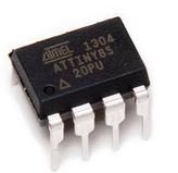
The "brains" of the automation board is an Atmel ATTiny85 Microcontroller - yes, an embedded computer. Some characteristics of the microcontroller are:
That's "b" as in bytes. While not nearly as powerful as the controller even in your cell phone, it is powerful enough to do the job. Perhaps though the best attribute of the microcontroller is it's low power the typical 80AH Deep Cycle battery, the run-time is an incredible 80,000hrs before it will fully discharge the battery. Programming note. The Atmel ATTiny85 must be programmed by the end user (you) for the board to function properly. Programming is not as difficult as you may think, and in fact, I have made the written program available so all you have to do is download it. You can use it as-is, or you can try your luck at programming and make changes as you see fit. The link below contain all of the instructions you will need.
Once you have the board, you will need a source of parts. I have located most of the parts from a great supplier: Tayda Electronics. They are located in Colorado, USA and ship domestically. The total cost for these items should be less $5. Tayda does have a $5 minimum, so look around, you might find something else to buy - or perhaps you may want to buy a couple of spare parts. For the few parts not available from Tayda Electronics, I recommend Digi-Key as they have inexpensive shipping for small parts. The critical part of the Digi-Key source are the LEDs - they have 1" long leads, which is necessary for the off-board mounting configuration. Other parts resources certainly have suitable LEDs, but be sure they have 1" leads. Secondly, if you are building the same version I did, Digi-Key has the switches, which are somewhat critical as they will fit into the small area available... and more importantly - the front panel and board are designed for those specific switches. Finally, a couple of specialty items need to be ordered. And the best source I have found for these is Amazon and eBay. Sometimes, those are the best source. I had considered making a limited run "kit" consisting of the printed circuit board, the components, and a pre-programmed ATTiny85, however, my license for use of the printed circuit board software is restricted to non-commercial use only.
Notes:
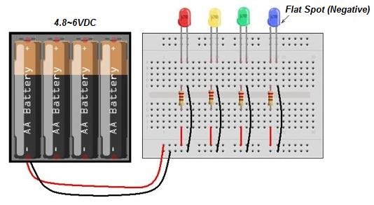
An easy way to test the LEDs is with an inexpensive breadboard as shown here. For just a few dollars, you can buy a breadboard with leads, battery tray, along with LED and resistor assortments (and you can re-use those parts in your project). Dependng on whether you use Alkaline or Ni-MH (EneLoop, etc) batteries and their state of charge, you will supply 4.8~6V or so on the LEDs, which is a close approximation to the 5V the LEDs are driven with in the monitor. Simply swap out resistor values until you find the desired brightness. You can use a resistor-substitution box, but you can run the risk of damaging the LEDs should you use too low of a resistor.
| |||||||||||