|
|
In order to program an ATTiny85, you need to accomplish a few tasks. First, you need to download the Arduino IDE (Integrated Development Envrionment), which is a fancy way to say the interface software for these microcontrollers. It is essentially the programmer. Ardunio is one of the public domain companies that was instrumental in the growth of microcontrollers for hobbyists, and their IDE is a free download.
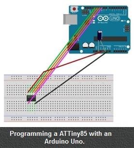
At this point, if you were able to get the LED blinky program to work (from the Arduino IDE Setup Guide), you are ready to continue. If not, YouTube has many videos on installing the Arduino IDE, and adapting it for the ATTiny85. Some of these resources are very good, so it is not necessary to replicate that information here.
When you download the file, unzip it by clicking on the folder. The .INO file should be extracted. Then, open the Arduino IDE and click "Open > File" and navigate to where the file is. You will be asked to create a new folder and move the file - select Yes. The file should then open.
Verify the settings of the Arduino IDE... from the main menu:
If you were successful in performing the LED test from the Sparkfun Tutorial (AVR Programmer Hookup Guide), these settings should already be made.
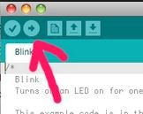
At this point, if not already done, insert the ATTiny85 into the Sparkfun Programmer and then insert the programmer into the USB port. Finally, you can upload the Charger/Battery Monitor sketch by clicking on the right-pointing arrow at the top of the screen. This should upload the sketch into the ATTiny85. If it did not work, make sure you did not make any changes to the sketch. Also, click "Tools > Port" and make sure the correct USB port is selected.
The sketch is written in C/C++, but don't let that intimidate you. The Arduino IDE and especially the ATTiny85 use a tiny portion of the programming capability. In the sketch, you will see many lines with a double-shash ( // ). This is a comment in the sketch and is skipped when the sketch is loaded. Essentially, the // are comments for the person writing the sketch.
Sooner or later, it's going to happen... you are going to get an error when you try to Verify or Upload the sketch into the ATTiny85. Most of the time, these errors are due to a misplaced symbol or mispelled command. To prevent this, you will at least need a rudementary understanding of the C/C++ programming language syntax. The most common errors are:
For this reason, after every couple of changes, click on the "Verify" menu selection to make sure you don't have an error. If you really mess up, you can always start over by downloading the sketch from this website.
So lets take a tour of the sketch and see what it does. All Arduino sketches have 3 sections:
Optionally additional sections (called functions) can be placed into the sketch. But we won't need to do that in this sketch as it is not very complicated.
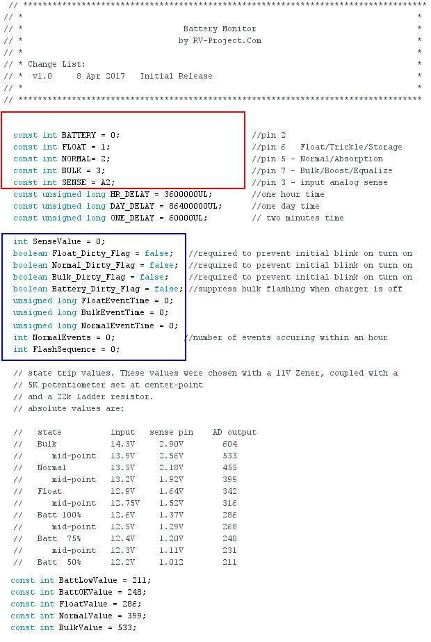 This first section is the declaration section. The lines in the red box define labels for each input/output pin of the ATTiny85. For example, "BATTERY = 0;" defines I/O pin 0, and will become the output pin for the Battery LED. Note that the pins here are logical pins (in this case 0), while the physical pin may differ (pin 2). In a similar case, pin's 1, 2, and 3 define the Float, Normal, and Bulk LED pins. Sense defines the Analog pin the A-D converter that will sense the voltage is connected to. It should be noted that any label name could be used, and in fact, labels are not even required. For example, instead of using the label "Sense" we could just use "A2". However, later in the program, you will be able to tell where the Sense circuit is being accessed a lot easier by naming it "Sense" rather than using A2. Using labels makes everything a lot easier to understand. The lines in the blue box contain variables. A variable is a place holder for a value. For example, in Algebra, if A=2, A is a variable that contains the number 2. And like Algebra, if A=2+1, then A will be updated to hold number 3. In this application, there are actually quite a few variables. "Int" means Integer, which means a whole number (not a fraction or decimal). Since the ATTiny85 has a limited amount of storage space, using integers whenever possible reduces the memory requred for manipulating that number, and keeps everything running fast. SenseValue the number of the A-D converter output after reading the voltage. The various "DirtyFlag" values help with the rather complex decision matrix, variables ending in "Time" hold the various timers used to flash the status LEDs. The last two variables hold the decisions from the decision matrix. The lines beginning with "const" mean they are constants - that is, non changing values. In that sense, they are not variables. They hold the numbers that equate to a certain time delay. The first set of constants simply define how many milliseconds there are in the various time delays, while the last set of constants hold the "trip points" between the different Charger/Battery modes.
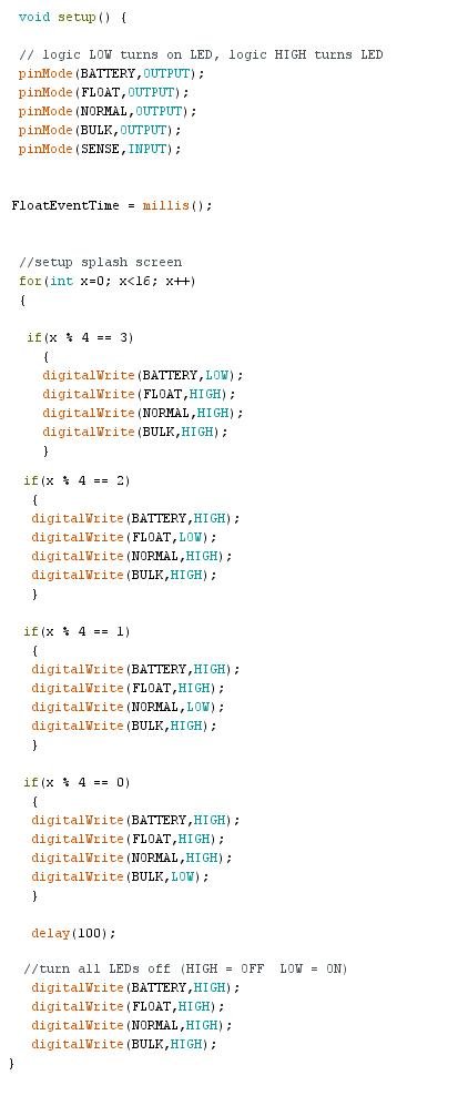 The second section is the Setup function. This a mandatory section and is run one time at the beginning of the sketch. It is used to setup the various hardware components of the ATTiny85 as well as any initial settings. The "pinMode lines are what actually defines each I/O port. For example, "pinMode(BATTERY,OUTPUT);" sets up the Battery pin (which was earlier defined as 0) as an output pin. BATTERY will be the line the Red LED will be connected to.
One pin is setup as input. pinMode(SENSE,INPUT) sets up the analog port A2 as an Input. Next comes the splash screen. A splash screen is the initial indicator that the board is working, and rapidly flashes the each LED 4 times. That way you know you turned the board on. A LOW turns the LED on, while HIGH turns the LEDs off The "for(int x=0;x<4,x++)" simply tells the ATTiny85 to run everything within the curly braces { } four times before continuing on.
The next thing that happens is the delay(100); This causes each LED pattern to remain on for 100 milliSeconds, or 1/10th of a second. The last lines turn the LEDs off - signaling the end of the "boot" sequence.
 Click on chart for an enlarged version.
The "Decision Matrix", which is the logic flow as to the behavor of the LEDs is actually a bit complicated. In fact, I ended up flow-charting the matrix (something I have not done since College). You may want to review the program flow while looking at the Loop section.
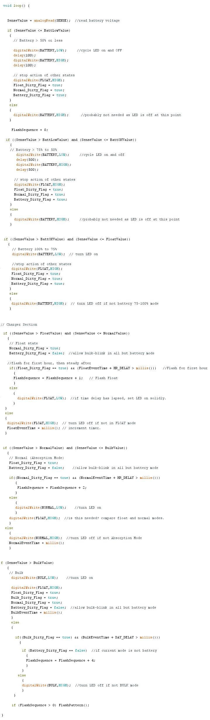 The third section, called the Loop, is by far the most sophisticated. Again, it is a mandatory section. After the Setup is finished, the sketch goes into the Loop section and stays there forever - or at least until the power is removed. The program execution starts at the top of the loop, then goes down line-by-line, executing the commands until it arrives at the bottom. Then it goes back up to the top of the loop and starts over again. It's sort of like the for loop we used above, except there is no counter to stop the loop. The first action to be taken "SenseValue = analogRead(SENSE)" reads the voltage on the Sense Pin and passes the voltage through the ATTiny85's internal Analog-Digital Converter, then places the result in the "SenseValue" variable. Next, an "if" statement is used to see if the SenseValue is less than the trip value of a battery that is discharged 50% or more. An "if" statement is a conditional statement, meaning something must be true for it to execute. There are two versions of the if statement; if and if/else. The if itself is the most basic, and if a certain condition is true, it executes the statement. If it is not true, it simply ignores the statement and goes to the next line (that is not within the if's curly braces). The second type; if/else will again execute the if statement if the condition is true, but will execute the else section if it is false. So in other words; an if statement is "do this if something is true" and the if/else statement is "do this if something is true, otherwise, do that".
The remainder of the loop statement simply looks at the SenseValue with if statements and executes the one that is true (or executes else statements for false if statements). In this sense, the if statements are a set of "windows" and the SenseValue must pass through one. Once the proper if statement is found, the LEDs are turned on, off, or blinked in accordance with the Decision Matrix.
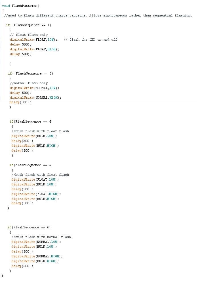 The last section, an independant function is declared. It must be noted that any additional functions are outside of the setup or loop functions. When called on, the program will branch to this function. The name of this function is called "FlashSequence" and is called on anytime the Bulk, Normal, or Float conditions are encountered. It's sole purpose is to flash the LEDs so they all turn on and off at the same time. Otherwise, two blinking LEDs would form more of a "Wig-Wag" pattern, which looks kind of silly.
Programming and uploading to the monitor.
The only likely program changes you would have to make is if you need to change the set points between the various modes. this is done at the very top of the sketch in the declarations section.
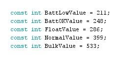
To change the setpoints, simply change the number in for the appropriate line. If for example, you decide you want to use an AGM battery, you would simply change the A-D values (after determining the proper voltages). See now why we use a variable for things like set points? If we did not use such variables, we might have to change 10 different lines of code... think you might make a mistake doing that? Also with all of the set points located together, it is easy to see what they all are. Otherwise, your need to use the Arduino IDE will be typically limited to downloading the sketch into the ATTiny85.
For those of you that have read this far, here is the last little tid-bit... programming the monitor to minimize the current demand in discharge mode. If you recall way back on page 1, I mentioned this as a way to reduce the load on the battery when boondocking. The code I will show you can be inserted to make the battery LED active 6sec every minute (or 1/10th of the time... resulting in a 90% reduction in the current demand).

These changes go into three areas. First, declare the "timer" in the declarations section. I named it "BatteryFlashDelay". Next, put the first if statement as the first line in the loop function. What this will do is to set the BatteryFlashDelay counter every 60seconds. For example as the system runs, the BatteryFlash Delay counter will be equal to 60000, 120000, 180000, and so on. It will not increment between the 60second updates. Lastly, wrap the last if statement around the specific battery LED flash commands. You will do this in three places. This if statement will add 6 seconds to the BatteryFlashDelay counter, and if the millis() counter is less, it will flash the LEDs. This condition will only be true in the first 6 seconds after the millis() updates the BatteryFlashDelay variable (which happens every 60 seconds). So the if statement will be true every 60 seconds for 6 seconds. Don't be afraid to experiment and try different things with the monitor programming.
References: AVR Tiny Programmer Sparkfun website for the ATTiny85 Programmer.
|