


|
|
After doing some research, it has become apparent to me that some RV'ers have issues with the Furrion camera, especially that they lose signal as they travel down the road (and are using the camera as an observation role). The primary reason for this I believe, is they are using the Furrion FRC12 Backup/Only camera when they should be using the more powerful Furrion FOS48 Observation/Backup camera. As well, there may be other issues, including antenna orientation, sufficient voltage to power the camera, and electrical interference generated by the tow vehicle.
Operational test video.
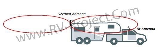
One thing I noticed - and experienced by others is that the angle of the antenna on the camera may not provide the best reception. The type of antenna used has a donut shape radiation pattern as shown (called omnidirectional). If you were to slice the donut down the middle, the radiation pattern would resemble a figure-8 laying on it's side. This is the characteristic of all "whip" antennas, like the one used on the camera.
The size and shape of the "donut" is highly dependant on the transmitter power (in this case, from the camera), as well as the antenna's gain. Typical antenna gains are 3dB, 6dB, 9dB, and 12dB. As shown, the higher the antenna gain, the flatter the donut. As well, as the donut "flattens" it becomes longer.
In practical terms, a higher gain antenna will exhibit a longer range front and back, with a more limited range above and below the antenna. Unfortunately, I do not have the specification for the antenna's gain used for the camera, but similar antennas of this fashion and length are in the 3~6dB range. So why is all of this important? The antenna's orientation is all-important for achieving the longest distance for reception of the signal. The maximum distance is dependant on the antenna's gain, as well as the vertical angle of the antenna. And the higher gain the antenna has, the more important the vertical angle is. For example:
Effect of raked antenna
When the antenna is raked back, the radiation pattern is not optimum, and can result in loss of signal intensity at the cab. If, however - the antenna were to have a vertical orientation, the front lobe of the radiation donut is lowered so that a much stronger signal may reach the receiver. Therefore, the single-most thing you can do to improve reception is to orient the antenna vertical. Howver, since the design of the camera favors a non-vertical antenna, you will have to re-orient it to the vertical. Luckily, the antenna has a "knuckle" that will allow this - but unfortunately, it may not stay put. Options are to use a bit of electrical tape, heat-shrink tubing, or even a dab of glue to orient the antenna vertically. So if you are having reception problems, try orienting the antenna vertically and see if it doesn't improve things.
 Vertical antenna
What about using a longer antenna? If you live in the United States, I advise against this, even though Furrion customer service has suggested using a longer antenna like the one shown to the right as a possible way to extend the range. While receiver antennas can generally be changed, there is a restriction (see FCC 47 USC Part 15 §15.203) that generally prohibits any modification of unlicensed-transmitters (those not requiring a license to operate), which would include lengthening the antenna to produce a stronger signal. The likelyhood of getting caught and fined is not an issue here - it is the issue of knowing what you can legally do and not do.
FCC Bulletin for Low Powered Unlicensed Devices (Sect 15)
Another issue that can affect camera range is powering the camera from a sufficient circuit. If powering the camera from an existing circuit, determine whether there is sufficient wire size to accomodate the camera. This is true anytime you add additional loads to DC circuits, but especially true when powering the camera from the tail-light circuit. Often these circuits can be overloaded due to the number of clearance lights the manufacurer adds to the trailer. For example, a trailer manufacturer may use 14SAE wire for the tail-light and clearance light circuits. While at first glance, the 14 gauge wire allowable 35Amp current rating would seem enough, you don't have the full picture without considering voltage drop. There are up to 16 light bulbs in a typical RV tail-clearance light circuit; two (or 4) for the tail-lights themselves, 5 clearance lights across the top rear, another 5 clearance lights across the front, and 4 side clearance lights. Say the tail lights consume 2Amps each, and the 14 clearance lights are #194 bulbs, with a 0.25A current demand each. So we are looking at around 7.5A full current demand. And consider the length of the wiring to be around 35 cable ft for a typical 30ft trailer. So lets say half of the clearance lights are the full 35ft, along with the tail-lights, and half of the clearance lights have a 10ft run.
Using my voltage drop caculator We find that the total voltage drop for this circuit will result in only 10.4V at the furthest bulbs where you will be tapping into for the camera. This may be acceptable for incandescant light bulbs as it is less than a 10% voltage drop. However, should you wire the camera to this circuit, we can expect an additional drop of 1/4Volt due to the camera's load (especially if you use the FOS48 Observation camera as it consumes more power), which results in the total voltage at the camera to be just a bit more than 10V. This is a low-voltage condition for an electronic circuit (3% or less is ideal), and while the camera may still function, it may have diminished range. The culprit here is not that the 14 gauge wire has enough current carrying capacity - it does. The problem is the excessive voltage drop along the wiring. The solution here would be to either run a dedicated power feed to the camera or swap out the lights for (DOT approved) LED equivalents, which should result in an overall voltage drop of less than 3%.
Video: Improving Camera Performance
You can also likely obtain a performance improvement by using RF Chokes on the DC power cable for both the camera and monitor. I have found that as you speed up down the road, you typically lose signal strength. This is not been a problem with the FOS48 as there is typically enough signal to overcome the signal loss. I believe a large part of the signal loss is RF interference; whether it be from electrical noise generated by your tow vehicle; spark plugs, brushes on the generator or motors, and the like. As well, adjacent vehicles passing by, or even overhead power lines could induce electrical noise. There are essentially three paths into the camera system from electrical noise. First, the antenna itself. However, the camera transmitter operates at 2.4Ghz, so it is fairly immune from the kind of noise that would typically be generated by towing. Secondly, noise can be injected right into the components of the circuit board. There is not a lot we can do to shield the board, but these days, there is typically a ground-plane built into the circuit board. Third, RF noise can be introduced into the power cable, because any length of wire can act as a rudementary antenna. It's this third form of interference that we aim to reduce by using RF Chokes.
Video: Improving Camera Performance - Part 2
The application of RF Chokes may or may not provide a significant result. It basically depends on whether there is any electrical interference to begin with. However, if you are traveling close to industrial areas, or vehicles around you (or even your own vehicle) are producing any amount of noise, the RF Chokes can help. I have found that the combination of techniques I have presented here - especially using the RF Chokes in addition to ensuring the antennas (especially on the camera) are vertical can add up. I rarely have less than "4-bars" (maximum) signal strength indication on my monitor after using these techniques. I show a few RF Chokes below. I have found the 3mm and 5mm ones to be the correct diameter for the typical power wires you will have for your camera.
After installing my camera, and with shared experiences of other owners, do NOT buy the Backup only camera (FRC12TA). Rather, consider only purchasing the Backup/High Speed Observation camera (FOS48TA). The cost differential is minor, and the FRC12TA will not provide sufficient signal when you are traveling down the road - it is for backing up only. Many owners are reporting loss of signal when using the Backup-Only camera while moving.
The Backup/High Speed Observation camera (FOS48TA) does not have this issue, as it maintains the signal while moving. I have noticed that the signal strength indicator on the monitor does drop when moving, but still maintains sufficient signal for using the camera. This has an advantage as you are on the highway and want to see behind you before changing lanes or for other purposes. Also, turn the camera off when you are not using it. If your camera is powered by the running lights, it will only be on when you turn your tow vehicle's headlights on. But if your camera is constantly powered by another circuit, make sure you put a on-off switch in the power feed. Leaving the power on constantly seems to burn out the cameras according to other owners I have talked with.
The photo on the left is the 4UCam Furrion adapter bracket, while the photo on the right shows the bracket in use. I am not sure about you, but that looks awful to me. It would be better to just remove the Furrion mount and be done with it. You may have to fabricate a square mounting plate behind the 4UCam mounting bracket to cover the Furrion bracket holes, but anything would be better than this!
References: Furrion FOS48TA Observation/Backup Camera Webpage
Furrion FRC12TA BACKUP ONLY Camera Webpage
|