|
|
It will be easier to wire the receiver into your RV's system if you know what happens each time a button is depressed on the remote. The following sequences were the more popular combinations you might find between the programming of a particular channel on the remote transmitter and how that channel behaves. The behavior is different depending on what kind of function you program; i.e. slide, light, vent, door lock, and so on. 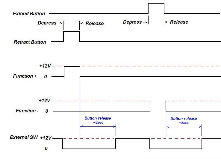 Reversing Channel (motor control) Behavior
Motor Reversing Function Behavior. When a Function channel is programmed as a slide control, the following behavior is observed.
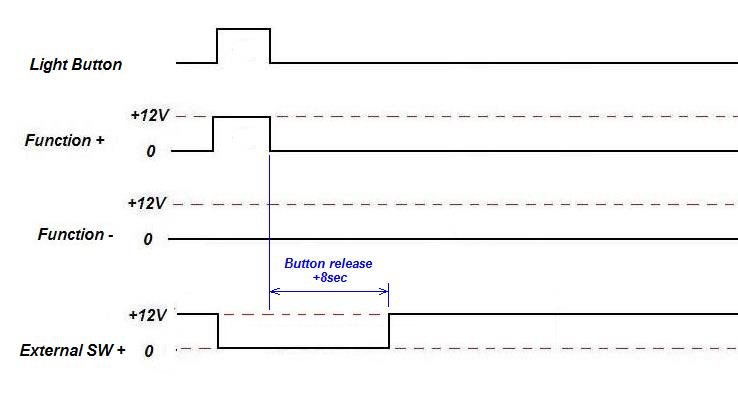 Function Channel programmed for lighting control.
When a Function is programmed in the remote as a light control channel, the channel on the receiver is setup to behave differently.
This presents a challenge when using a function channel as a light control, as if a light is directly connected to the channel, it will only be on while you are dpressing the button on the remote. As soon as you let go of the button, the light will go out. What is required is either a light fixture that can be turned on-off with a momentary pushbutton, or an external adapter board that latches the pushbutton action into an on-off sequence.
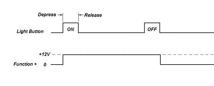 Light Channel Behavior
. This behavior is limited to the single Light Channel found on either 5-function or 8-function receiver board. It is hard-coded into the system and cannot be changed. One advantage of this function is that it is available on both the main menu on the wireless remote without having to enter a PIN, as well as it is always the first function in the remote's menu after you unlock it with your PIN. Simply, whenever the LIGHT button is depressed on the wireless remote, the output toggles from ON to OFF. In the ON state, +12VDC is applied to the Light terminal, and in the OFF state, the voltage on the terminal returns to 0VDC. There is no change in the status of the External SW terminals when operating the light function.
During my initial analysis of the receiver board, I tried many different combinations; programming a light function in each channel independantly; using a different fuse for each channel, and so on. I was attempting to discover some "magical" combination that might put the channel into a latching mode more suitable for lighting control, but I was not able to find any such feature. Too bad the manufacturer didn't spend the resources in coming up with a fuse programming feature in developing a latching feature instead.
 Typical wiring scheme
Consider the diagrams you see here generic. This is the basic wiring configuration that Lippert provides in their manuals. Module-controlled motors such as the Schwintek systems may require additional configuration methods, as well as possible adapter circuitry to safely function. I am providing the behavior of the receiver as I have experienced it. Connection is up to you to figure out.
 Function (reversing motor) Switch Wiring
The above schematic shows what happens when the Function channel is wired for a standard (i.e. directly connected) motor. When the remote transmitter is not active, +12V is applied from one of the External Switch + terminals (remember, two are fused and one is not). The three terminals allows some degree of load-balancing. For example, should there be a motor with high current demands, it will likely work better if it uses it's own External Switch channel. This of course all depends on the types and quantities of slide and awning motors you wish to control. The proper wiring configuration is up to you. With +12V applied by the External SW terminal, manual control of the slide is possible by using the remote switches on your RV's control panel. However, when the receiver is commanded to operate a slideout via the wireless remote, 12V is removed from the external switches as the External SW + channel goes to 0V. Then, depending on which button was depressed (RETRACT or EXTEND), 12V is applied to one of the Function terminals, and GROUND is applied to the other. This causes the slide or awning motor to move in the appropriate direction. Then, 8 seconds after release of the remote transmitter button, 12V is again applied to the control panel switches by the External SW + terminal returning to 12V. The action of the External SW + terminal ensures that you cannot short the battery to ground by depressing the EXTEND button on the wireless remote while at the same time depressing the RETRACT button on the control panel. You should obviously never do this, but using the External SW function prevents this from happening. Unfortunately, not all motor reversing switches are the same. There are two versions of identical looking switches that I am aware of; a standard motor reversing switch (with motor open at rest) and a reversing switch with parking (with motor grounded at rest). You may encounter either one when adding remote control to your RV, and the wiring scheme is different for the parking version (the standard version is wired as shown above).
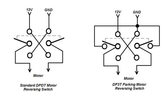
As shown above, the primary difference with the motor switch is the motor is grounded. If you attempt to use the Linc controller with this switch as shown above, you will short 12V to ground - not good. Therefore, an intermediate set of relays can be used to prevent this.
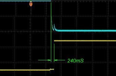
 (blue and yellow flags represent the connections for the oscilloscope trace below)
As shown in the oscilloscope trace to the right, the Yellow channel (1) is connected to the Channel Output, while the Blue Channel (2) is connected to the Ground (the voltage is inverse on the oscilloscope display for the Blue Channel simply as a function of measurement). There does seem to be a slight delay wherein the Ground (Blue) is removed prior to application of 12V on the switch (Yellow). Testing has revealed the delay to be around 240mS - or 1/4 Sec. between the time the Ground is removed and Power is applied to the relay from the remote panel. So this is indeed a "break before make" switch situation. Whether or not this is sufficient is debatable, but I would like to see a bit more delay. So if it were me, I might add the additional relays for safety sake.
You can use your own method of determining whether the inherent delay is sufficient to prevent shorting 12V to GND when using a parking type switch, however at least for other types of remote receivers (i.e. the typical 433Mhz Wireless Relays), the additional relays may be required.
RV Motor Control Switch Types.
 Light Switch Wiring
The single light switch channel is pretty easy. The receiver can be wired to the light switch on your RV (assuming you can access it). There is no need for connecting the External SW + terminals as the configuration does not present a case where a short across the battery could occur.
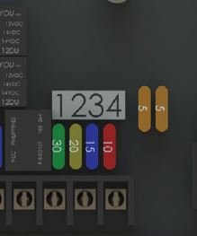
I suppose it now comes down to obtaining the 4-digit PIN for the fuse menu in the wireless remote. The menu allows you to assign one of 4 fuses to one of 4 channels. For the life of me, I do not understand why they even bother.
For example, for the 5-Function receiver, the light channel has it's own dedicated on-board fuse, so you are going to program 4 fuses to 4 channels? Give me a break. Why don't they just dedicate fuse 1, 2, 3, and 4 to Channel 1, 2, 3, and 4. Duh! I would really like to hear a Dave Jones (EEVBlog.com) expletive right now. True, the 8-Function receiver has 7 channels that must be programmed to 4 fuses, so you have to share them between channels. But why not just add 3 more ten cent fuses on the motherboard and be done with it? The manufacturer probably spends a significant amount of money on each board for in reality an un-needed function, yet the RV industry won't spend any money to improve the tank monitor systems? Incredible.
Just in case the lawyers do have a legitimate liability concern and my not wanting to be sued, I am not going to tell you the PIN. But I will tell you that Lippert has published the 4 digit PIN on this page of their website (you may have to look a bit to find it, but it's there).
Remote Controlling the RV with the Lippert Linc Receiver.
|