


|
|

Just when you thought you have seen it all, I have added several add-ons for the dimmer, including several daughter boards and different switch/control combinations. The add-ons include:
These adapters work for both high-side and low-side boards. In some cases (i.e. the power adapter), there are different versions for high/low side boards. The other adapters will work regardless of board type.
The switch/control boards provide a wide variety of control options. If you recall, the most simple option is for a push-button switch, as there is an on-board dimmer control that can be preset if desired. The following switch/control boards include:
Note that these options require ver 1.4 or later of the Linc Board Driver sketch, which is available below:
Detailed construction details, schematics, bill of materials, and notes for construction of the adapter boards and switch/control modules are available from the link to the right. Perhaps the most difficult part of the dimmer is deciding which set of controls you want for your RV:
For example, I am using the wiring configuration shown here. It consists of a momentary switch on the console panel which replaces the original on-off switch. The momentary switch will provide ON-DIM-OFF functionality with each depression of the switch. And I will wire a control module consisting of a dimmer control, with an ON-OFF switch on the potentiometer so I can turn off the dimmer (Zero mA option), and finally, an Auto-Off switch so I can utilize the 4hr time-out function.
The basic wiring configuration is shown below:

The schematic shown here includes the Switch/Control module and Momentary Switch located in the control panel. I will also be using a Wireless Relay (at least temporarily) for the second channel.

And the wiring interface to the dimmer module is shown above. The letters A-E correspond to the connectors A-E in the previous schematic. The PDF documentation has additional information on the construction of the modules used in this configuration. You can download the front panels detailed in the construction plans here:
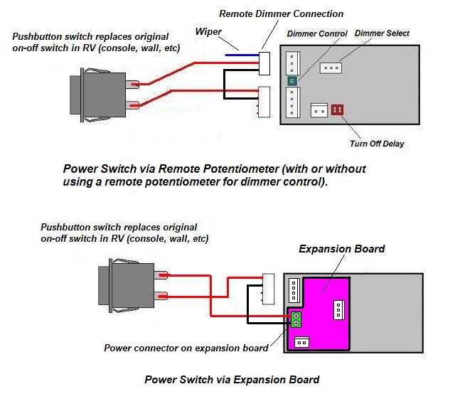
Here are 4 different configurations that are possible. Note that this is just the beginning, and you can wire the dimmer board in so many different ways. These drawings were made some time ago, so note that the actual location of the connectors on the dimmer have changed - but not the function of the connectors.


Alternative methods of powering the minimum configuration momentary switch. Power is available from pins 1 and 2 of the remote dimmer potentiometer. This is useful for providing power to the switch from the board. This scheme can be used whether or not the remote potentiometer is also used. Several of the add-on switch/dimmer modules use this approach. If you are using an expansion board, power is also available from a terminal block on the board.
|

