
|
|
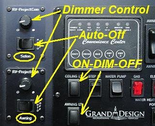
I am installing two of my dimmers in my RV; one for the 5 overhead LED puck lights in the Salon, or main living area, and the second one for the outside awning strip-light. Due to the configuration of the existing wiring, I will be using high-side dimmers. And I decided on a combo panel for the dimmer control which has an auto-timeout feature.
I am also using the power adapter board so that I can completely turn the dimmers off when not using them. There is somewhat of a tradeoff when using the power adapters. The chief purpose of the adapter board is to eliminate the idle current when the lights are not needed. Without the adapters, there is around 0.007A (7mA) of idle current consumed, even when the lights are off. This overhead comes from the fact the dimmers must be powered to receive commands to turn the lights on or off. When using a power adapter board, there is Zero current consumed when the dimmers are turned off (essentially they are powered down). However, this does come with a penalty in that a 40ma (0.04A) standby current is required when the dimmer is in operation and the lights are off.
The following table can explain the different modes of operation:
The table shows that with the power adapter, when the system is OFF, zero current is consumed vs 7mA (per dimmer) when not using the power adapter. That is the boondocking savings. However, when the dimmer is in standby or in use, 40mA is consumed, which accounts for the relay module. Still, if you dim the lights in a boondocking situation, you are still ahead in power consumption vs. not using a power adapter.
 > >Figure 1
This is the basic wiring configuration for the installation. Since I am using two dimmers, I need two of everything. The details for how to construct the wiring harness, parts list, and panel templates are shown in the Add-On page. However, you can download the requred information from the link to the right: Also the latest version of the Linc Board Driver sketch should be used, and set to "configuration 2" (explained in the sketch).
 Figure 2
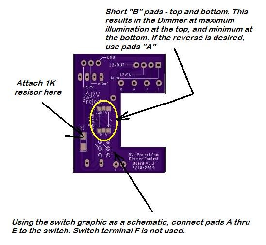
The designators A-E on the schematic correspond to A-E on the graphic of the dimmer board. I also created a panel board made of 1/8" fiberglass to assist in installing the dimmers into the cabinet. The components mount onto the panel board, then the panel board mounts into the cabinet. It's a lot easier than trying to mount each component individually and wiring them.

I also attached two eMylo receivers, set to Momentary temporarily, until I can work on the automation project. Eventually, I will replace the receivers with one of my own design, complete with Bluetooth/WiFi connectivity so the dimmers can be controlled via smartphone. But for now, I will settle on wireless control of the dimmers with a hand-held transmitter. The maroon-color on the screws is a Red Electronics varnish - called Glyptol, that keeps screws from falling out due to vibration.
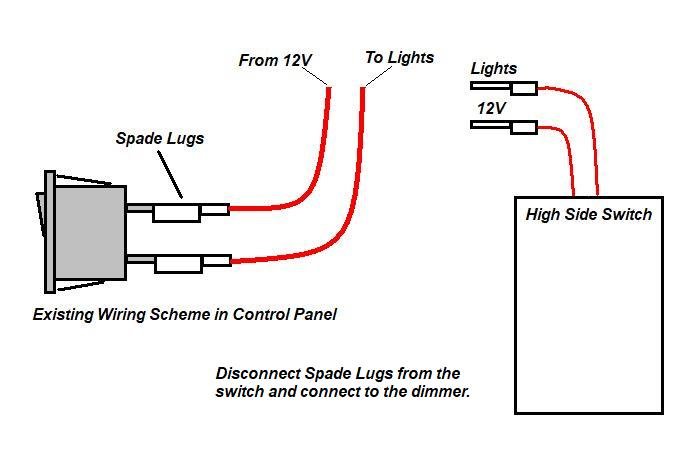 > >Figure 3 Connection into the existing wiring was quite easy. I simply made a couple of "pigtails" with (male) spade lugs and attached them to the dimmers. All I had to do is disconnect the spade (female) connectors from the switch and re-connect them to the lugs on the pigtails.
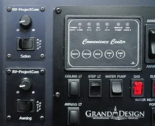
Spouse Designed Dimmer ControlAfter a year of use, my wife did not like my dimmer control, she said; "fix it so it is easier to use". So here is Version 2 of my dimmer control used in the control console. This is an asthetic change... all of the functions are the same, but the control layout is a bit easier. The changed I made were:
The wiring of the new module is the same as Figure 1, so no changes there.
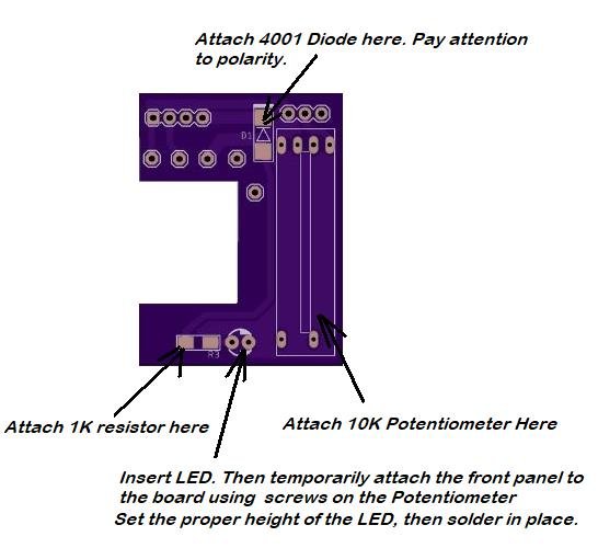
Note, RED, WHITE, GREEN, ORANGE, and AMBER LED potentiometers are available, as well as having no LED.
 Circuit Board Front
 Circuit Board Rear
Refer to Figure 1 for final wiring.
| ||||||||||||||||||||||||||||||||||||||||||||||||||||||||||||