|
|
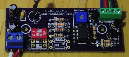 Automation Board - Option 2 (RGB Version).
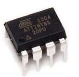
The "brains" of the automation board is an Atmel ATTiny85 Microcontroller - yes, an embedded computer. Some characteristics of the microcontroller are:
That's "b" as in bytes. While not nearly as powerful as the controller even in your cell phone, it is powerful enough to do the job. Perhaps though the best attribute of the microcontroller is it's low power consumption. We will be running the controller at 1Mhz and 3.3VDC, which results in a 1mA consumption. We could go even lower, but with the 2000mAH battery we will be using, this device can run for 83 days! Of course, that is in standby mode - i.e. in the daytime without the LEDs active.
Programming note. The Atmel ATTiny85 must be programmed by the end user (you) for the board to function properly. Programming is not as difficult as you may think, and in fact, I have made the written program available so all you have to do is download it. You can use it as-is, or you can try your luck at programming and make changes as you see fit. The link below contain all of the instructions you will need.
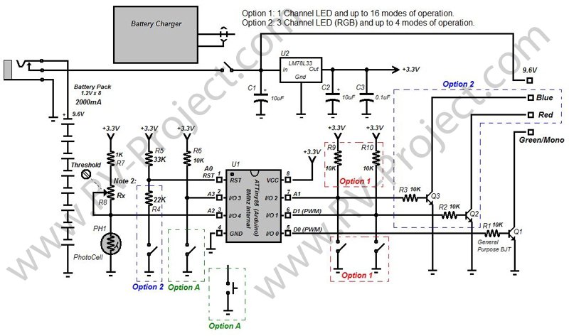
This board can be made as a RGB or Monochrome (single color) board. You will need to decide which option you want. Option 1 is for the Monochrome version and Option 2 is for the RGB version. Option 1 provides up to 16 different flash patterns that you can program, while Option 2 is limited to 4 patterns. For this reason, Option A can be used with Option 2 to extend the number of patterns by allowing the pattern to be changed each time you depress the switch. This can provide an endless number of flash patterns - up to the memory limits of the ATTiny85.
Since the output channels of the ATTiny85 are limited to a few mA at 3.3V, output transistors are used (Q1, Q2, and Q3) that not only power the LED strips at 9.6V, but also can provide up to 800mA of current to the LEDs, which is sufficient for the 3ft LEDs.
Inputs: Pins 1, 2, 6, and 7 (Option 1) or Pins 1 and 2 (Option 2) are used for inputs. They read the switch position of the DIP switch, and select the proper flash pattern. The binary system is used here, which provides 2x selections per position. In other words, a single switch will provide 2 states, two switches, 4 states, 3 switches = 8 states, and 4 switches = 16 states. Therefore, 2 switches (Option 2) will provide 4 different flash options while 4 switches (Option 1) will provide up to 16 different patterns. The resitsors R6, and optionally R9, and R10 are known as "pull up" resistors and ensure a Logic 1 value is presented to the ATTiny85 when the switches are off, and a Logic 0 value when they are closed. Resistor R4 and R5 are a special condition. Normally the ATTiny85 reserves Pin 1 as a reset pin, and if a Logic 0 is applied as it is done with the other inputs, the microcontroller will be continuously reset, and no operation will be possible. However, by treating this input as an analog input, and selection of the resistor values as shown, we can change the input enough that the ATTiny85 can detect the switch position, yet not enough to reset the microcontroller. Again, this is setup in the programming.
Pin 3 is also setup as an analog input, and reads the voltage on the photocell. In bright light conditions, the photocell's resistance will be less than in low light conditions. So when coupled with R8, the voltage on the photocell will decrease in the daytime and increase at night. The ATTiny85 can detect this for dusk-to-dawn operation. R8 is a potentiometer (variable resistor), and it's function is to calibrate at which point the photocell trips the automation. If the automation starts when it is too bright, then turning R8 one way will cause the photocell to trip in lower light. And turning R8 the other way will increase the trip point.
It should be pointed out that the selection of R8 is highly dependant on the photocell being used. I strongly suggest using the photocell available in the Bill-of-Materials list, as I selected R8's value for this photocell. If you use a different photocell, you may find you will need to either change R8 to a different value, program a different threshold value into the ATTiny85, or both. Power Supply: U2 and C1, C2, and C3 are the power supply for the board, and provide a regulated 3.3VDC @ 100mA to power the ATTiny85. The ATTiny85 can operate from 1.8 to 5.5V (depending on version), and 3.3V is sufficient for proper operation and low power consumption. Basic Operation: The ATTiny85 will monitor the photocell's value once per second. If the photocell is properly adjusted, at dusk, the photocell's value will trip the threshold of the input pin causing the ATTiny85 to go into active mode and flash the LEDs in accordance to the sequence selected by the switch, and programmed into the microcontroller. This pattern will continue until the timer has expired (one, two, or four hours) as programmed into the microcontroller, or until the photocell detects dawn has arrived. In reality though, since you can program any sequence or delays into the microcontroller, an almost endless pattern can be created.
Once you have the board, you will need a source of parts. I have located all of the parts from a great supplier: Tayda Electronics. They are located in Colorado, USA and ship domestically. The total cost for these items should be just under $5. Tayda does have a $5 minimum, so look around, you might find something else to buy - or perhaps you may want to buy a couple of spare parts. I had considered making a limited run "kit" consisting of the printed circuit board, the components, and a pre-programmed ATTiny85, however, my license for use of the printed circuit board software is restricted to non-commercial use only.
Note on quantity. The resistors come in a pack of 10. The Quantity needed columns for Option 1 and Option 2 reflect the number of items required when ordering, not necessarily how many items used per option. For example, 4ea 10k resistors are required for both Option 1 and Option 2, however, only qty 1 needs to be ordered as they come in a pack of 10.
Construction is primarily populating the circuit board with the proper components. This is typically done step-by-step inserting a few components at a time, then inserting them. If you have never soldered before, I would recommend practicing a bit.
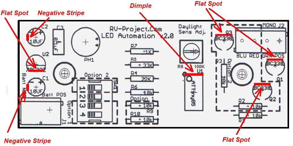 Parts Locator and Polarity Orientation
Reference part on the Bill-of-Materials and install as shown on the Parts Locator above. Pay attention to orientation and polarity for the transistors (Q1, Q2, Q3), ICs, (U1 and U2) and Electrolytic Capacitors (C1 and C2). No other parts are polarity sensitive and can be inserted either way. When you are done, if you built Option 1, there should be no resistors in R2 or R3, no transistors in Q2 or Q3, no connector in the left side of J2, and a 4 pole switch S1. If you built Option 2, there should be no resistors in R9 or R10, and S1 should be a 2 pole switch with the switch located at the top (the bottom 4 holes should be open). With these exceptions, there should be parts in every location. For C1 and C2, the Negative Stripe should be to the Left when the board is oriented as shown. The flat spots for Q1, Q2, and Q3 should be pointed up, and the flat spot on U2 should be pointed down. The dimple in the socket for U1 should be pointed up.
Project Video.
References: Order the Circuit Board Here OSH Park.Com
|